VIDEO TUTORIAL: Video tutorial available online for Continuous Ambient Compensator.
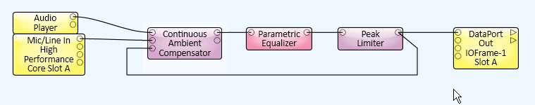
The Continuous Ambient Compensator is used to control the level of a program, for example background music or announcements, in a situation where the ambient signal level varies.
The ambient signal level is measured, and as it rises, the gain applied to the program material is increased, so that the program material can be heard over the ambient signal. The ambient signal level is measured continuously, even when program material is present. The ambient compensator removes as much program material from the sensing microphone signal as possible by modeling the path from the loudspeaker(s) to the sensing microphone.
Program - Connect the program material to this Input Pin, for example background music or announcements. If the program material is more than one channel, it should be summed to one channel for this input.
Microphone - Connect the ambient sensing microphone to this Input Pin. If multiple sense microphones are used, mix them and feed the mix to this input.
Reference - Connect the program material taken from the output that feeds the amplifier(s) after it has been post-processed by any filters/equalizers and non-linear components such as compressors and/or limiters.
Program - The program material with the Continuous Ambient Compensation gain applied.
Ambient - Monitor output of the actual recovered ambient signal.
|
Control |
Function |
Default/Range |
|---|---|---|
|
In Gain (dB) |
Adjusts the microphone input level. |
Default = 0 Range = -20 to 20 |
|
Detector (dB) |
Displays the ambient level, including any program material present. |
Range -60 to 20 |
|
Response Panel |
Graphically displays the operation of the Continuous Ambient Compensator. The X axis represents the recovered ambient signal RMS level. The Y axis represents the dB gain that is applied to the program material. |
N/A |
|
Bypass |
When engaged, the Continuous Ambient Compensator is bypassed. |
Off/On |
|
Gain (dB) |
Displays the gain applied to the program material. |
Range -60 to 20 |
|
Out Gain (dB) |
Adjusts the Program output level. |
Default = 0 Range = -20 to 20 |
NOTE: Depending on the Type of filter you select, some of the controls listed below may not be available.
|
Control |
Function |
Default/Range |
|---|---|---|
|
Bypass |
When engaged, the Mic Filter is bypassed, the ambient noise is not filtered except by the Audio Bandwidth setting in the Properties. |
Off/On |
|
Type |
Selects the type of filter to use. |
Low-Pass High-Pass Band-Pass Band-Stop Parametric Low-Shelf High-Shelf |
|
Bandwidth (Octave) |
Sets the width of the frequency band to be filtered. Available only with the Band-Pass, Band-Stop, and Parametric filters. |
Default = 1 Range = 0.01 to 3.00 |
|
Frequency (Hz) |
Sets the frequency of the filter. For filters that have a bandwidth setting, this is the center frequency of the bandwidth. The upper limit for this control is either 1.25 kHz, 2.5 kHz, or 5.0 kHz depending on the Audio Bandwidth Property. |
Default = 100 Range = 10 to 5000 |
|
Gain (dB) |
Sets the gain for the Parametric, High-Shelf, and Low-Shelf filters. |
Default = 0 Range = -100 to 20 |
|
Control |
Function |
Default/Range |
|---|---|---|
|
Mic/Spkr Distance (meters) |
The distance, in meters, between the microphone and the nearest loudspeaker. If this control is set to less than the actual distance, the compensator wastes cycles modeling the propagation delay from the loudspeaker to the microphone. If the microphone is not too far from the loudspeaker, the compensator continues to work but with a higher risk of program material leaking into the recovered ambient signal. If the entered Mic/Spkr distance is greater than the actual distance, the compensator will be unable to model part of the response, and program material will leak into the recovered ambient signal with possible runaway gain as a result. The Continuous Ambient Compensator works with multiple loudspeakers, provided they are driven with the same program material, and this control is set to the distance to the nearest loudspeaker. |
Default = 0.00 Range = 0 to 10 |
|
Detector Time (seconds)
|
The Detector Time control is available when you have selected Use Control for Detector Time in the Properties. The Detector Time determines the rate of change of the Detector level in response to changes in the ambient input signal. |
Default = 1.00 Range = 1.00 to 60
|
|
Program Cancellation (dB) |
This meter shows the amount of program material that the component was able to remove from the sense microphone. |
N/A |
|
Control |
Function |
Default/Range |
|---|---|---|
|
Ambient Threshold (dB) |
The recovered ambient signal level at which the compensator starts compensating. (The program material already has been removed.) Represented in the Response Graph as the lower of the two blue dots. When this control is moved, the blue dot moves horizontally on the X axis. |
Default = -30 Range = -60 to 20 |
|
Ratio |
A value of 1 results in a gain change that matches the ambient signal level change. A value of 0.5 results in 0.5 dB of gain change for every 1 dB of ambient signal level change. A value of 2 results in 2 dB of gain change for every 1 dB of ambient signal level change. |
Default = 1 Range = 0.2 to 2.0 |
|
Minimum Gain (dB) |
The minimum amount of gain you want to apply to the Program output when the ambient noise is at it's lowest point. Usually a negative amount, or attenuation - shown in red on the Gain meter. Gain is added to the Program input level up to this setting. If the Minimum Gain is -15 dB, and the Program input level is 5 dB, the Program Output is -10 dB 5 + (-15) = -10 Represented in the Response Graph as the lower of the two blue dots. When this control is moved, the blue dot moves vertically on the Y axis. |
Default = -10 Range = -20 to 0.0 |
|
Maximum Gain (dB) |
The maximum amount of gain you want to apply to the Program output when the ambient noise is at it's highest point. Gain is added to the Program input level up to this setting. If the Maximum Gain is set to 10 dB, and the Program input level is 5 dB, the Program Output is 15 dB. Represented in the Response Graph as the upper of the two blue dots. When this control is moved, the blue dot moves vertically on the Y axis. |
Default = 10 Range = 0 to 20 |
The time constant is the time it takes to cover 63% of the control change. For Attack, the start gain is 1.0 (unity) and the end gain is 0. After 10 seconds, the value is at 1-0.63 = 0.37, which corresponds to -8.7 dB. For Release, the start gain is 0 and the end gain is 1.0 (unity). After 10 seconds, the value is at 0.63 which corresponds to -4 dB. Depth is ignored in this calculation, it simply limits the filtered gain to a minimum.
|
Control |
Function |
Default/Range |
|---|---|---|
|
Attack Time (seconds) |
Determines the time it takes for the gain to reach 63% of a rising ambient signal detector level. |
Default = 1 Range = 1 to 60 |
|
Release Time (seconds) |
Determines the time it takes for the gain to reach 63% of a falling ambient signal detector level. |
Default = 1 Range = 1 to 60 |
|
Property |
Function |
Choices |
|---|---|---|
|
Audio Bandwidth |
Since lower frequencies are dominant in most ambient signals, the Continuous Ambient Compensator provides the capability of specifying the upper limit of the audio bandwidth used to measure for compensation. Lowering the upper limit of the audio bandwidth causes the compensator to use fewer resources. This property does not affect the program material audio bandwidth, which is always full bandwidth. |
1.25 kHz 2.5 kHz 5.0 kHz |
|
Microphone Filter |
Determines if the Mic Filter is active and available in the Control Panel. |
Yes / No |
|
Relative Venue Size |
This determines the size of the loudspeaker(s)-to-microphone or system response modeler. The smaller the model, the fewer the processing resources required by the component. If the Continuous Ambient Compensator does not sufficiently remove the program material from the microphone signal, increase the venue size. |
1 to 10 |
|
Detector Time (seconds) |
Selects a preset Detector Time, or enables the Detector Time control in the Control Panel. |
Use Control 1 10 60 |
The available Control Pins depend on settings in Properties.
|
Pin Name |
Value |
String |
Position |
Pins Available |
|---|---|---|---|---|
|
Ambient Detector Level |
-100 to 20 |
-100 dB to 20 dB |
0.000 to 1.00 |
Output |
|
Ambient Microphone to Nearest Speaker Distance |
0 to 10 |
0 mm to 10 m |
0.000 to 1.00 |
Input / Output |
|
Ambient Threshold Level |
-60 to 20 |
-60 dB to 20 dB |
0.000 to 1.00 |
Input / Output |
|
Applied Gain |
0 to 20 |
0 dB to 20 dB |
0.000 to 1.00 |
Output |
|
Attack Time |
1 to 60 |
1 s to 60 s |
0.000 to 1.00 |
Input / Output |
|
Bypass |
0 1 |
active bypass |
0 1 |
Input / Output |
|
Detector Time |
1 to 60 | 1.00s to 60.0s | 0 to 1.00 | |
|
Input Gain |
-20 to 20 |
-20 dB to 20 dB |
0.000 to 1.00 |
Input / Output |
|
Maximum Program Gain |
0 to 20 |
-20 dB to 20 dB |
0.000 to 1.00 |
Input / Output |
|
Microphone Filter Bandwidth |
.010 to 3.00 |
.010 to 3.00 |
0.000 to 1.00 |
Input / Output |
|
Microphone Filter Bypass |
0 1 |
active bypass |
0 1 |
Input / Output |
|
Microphone Filter Frequency |
10 to 5000 |
10 Hz to 5 kHz |
0.000 to 1.00 |
Input / Output |
|
Microphone Filter Gain |
-100 to 20 |
-100 dB to 20 dB |
0.000 to 1.00 |
Input / Output |
|
Microphone Filter Type |
1.00 2.00 3.00 4.00 5.00 6.00 7.00 |
Low-Pass High-Pass Band-Pass Band-stop Parametric Low-Shelf High-Shelf |
0 .167 .333 .500 .667 .833 1.00 |
Input / Output |
|
Minimum Program Gain |
-20 to 0 |
-20 dB to 0 dB |
0.000 to 1.00 |
Input / Output |
|
Output Gain |
-20 to 20 |
-20 dB to 20 dB |
0.000 to 1.00 |
Input / Output |
|
Program Cancellation |
0 to -20 |
0 dB to -20 dB |
0.000 to 1.00 |
Output |
|
Ratio |
0.200 to 2.00 |
.200 to 2.0 |
0.000 to 1.00 |
Input / Output |
|
Release Time |
1 to 60 |
1 s to 60 s |
0.000 to 1.00 |
Input / Output |
© 2009 - 2016 QSC, LLC. All rights reserved. QSC and the QSC logo are trademarks of QSC, LLC in the U.S. Patent and Trademark office and other countries. All other trademarks are the property of their respective owners.
http://patents.qsc.com.
![]()
 Related Topics